1 Judge others with kindness
2 Remember to express gratitude
3 Learn to accept criticisms without taking offense
4 Focus on the needs of others
5 Handle interruptions creatively
6 Learn the value of silence
7 Give a little extra
8 Work toward the goal of accepting and loving your self
9 Accept your emotions as valid
10 Accept LIFE
Thursday, April 8, 2010
Thursday, March 11, 2010
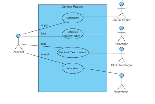
use case diagram of the pre enrollment process of USEP
GENERAL STRUCTURE
BREAK-DOWN STRUCTURE
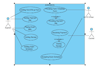
Use Case Name: Admission Process
Actors: Aspirant, UGTO Officer and the Cashier
Description: The Use Case describes the flow of event during the admission proper in the university.
Triggering Event: The aspirant arrives to UGTO Office.
Basic Course:
1. Aspirant gets and fill-up form.
2. UGTO Officer receives and checks the form.
3. If correctly filled-up, UGTO provides payment slip
4. Aspirant submits slip and pay bills to cahier.
5. Cashier receives the payment and issue receipt.
6. Aspirant show receipt to UGTO Officer.
7. UGTO Officer assigns examination schedule.
8. Aspirant gets the schedule.
9. End of Use case.
Pre-Condition: none
Post-Condition: The aspirant now has examination schedule.
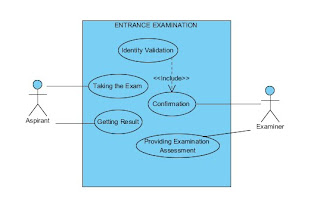
Use Case Name: Entrance Examination Process
Actors: Aspirant, and Examiner
Description: The Use Case describes the flow of event during the entrance examination proper in the university.
Triggering Event: The aspirant arrives to examination room assigned to her/him.
Basic Course:
1. Examiner checks the validity of aspirant.
2. If valid, aspirant may now take the exam.
3. If done, the examiner assesses the exam.
4. The examiner afterwards generates results.
5. Aspirant gets the exam results.
6. End of use case.
Pre-Condition: The aspirant has his/her assignation for the exam.
Post-Condition: The aspirant has his/her entrance exam result.
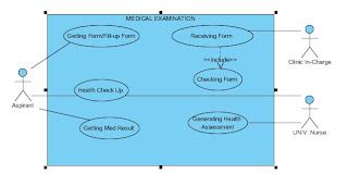
Use Case Name: Medical Examination Process
Actors: Aspirant, Clinic In-Charge, Univ. Nurse
Description: The Use Case describes the flow of event during the medical examination proper in the university.
Triggering Event: The aspirant arrives to the clinic.
Basic Course:
1. Aspirant gets and fill-up form.
2. Clinic In-Charge receives and checks the form.
3. If correctly filled-up, aspirant will be check-up by the Univ. Nurse.
4. Univ. Nurse generates Medical Assessment.
5. If passed, aspirant now get the assessment.
6. End of use case.
Pre-Condition: The aspirant passed the entrance examination.
Post-Condition: The aspirant has her/his medical exam result.
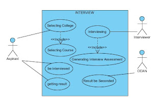
Use Case Name: Interview Process
Actors: Aspirant, Interviewer, DEAN
Description: The Use Case describes the flow of event during the interview proper in the university.
Triggering Event: The aspirant arrives to the room allocated for interview.
Basic Course:
1. Aspirant chooses a college and a course.
2. Student must be interviewed.
3. In-charge interviewer conducts the interview.
4. In-charge interviewer assesses the interviewee.
5. If pass, aspirant name will be posted.
6. The result will be seconded by the Dean.
7. End of use case.
Pre-Condition: The aspirant passed the medical examination.
Post-Condition: The aspirant passed the interview and may enroll now as student of the university.
Wednesday, March 10, 2010
Lightning-fast Internet could be reality
Cisco Says New Router to "Forever Change the Internet": The Question Is 'When?'
Posted Mar 09, 2010 07:44pm EST by Peter Gorenstein
Reposted Mar 11, 2010 12:08 glecy may dapal
Editor's note: Cisco made headlines today announcing a next generation router that will revolutionize the internet by increasing downloads to unheard of speeds. The Cisco press release makes the following claims about the CRS-3 router:
It enables the entire printed collection of the Library of Congress to be downloaded in just over one second; every man, woman and child in China to make a video call, simultaneously; and every motion picture ever created to be streamed in less than four minutes.
Tech Ticker interviewed Kelly Ahuja, Cisco Senior Vice President and General Manager Service Provider Routing Technology Group about the new product this afternoon. He answered all our questions but one: When will consumers be able to take advantage of this new high speed internet? Perhaps that's because that part of the equation is up to our internet service providers. Until they upgrade it might as well all be a dream.
Below is Kara Swisher's take on the new product.
Provided by All Things D, March 9, 2010:
Cisco today announced a new version of its key routing system, which the networking giant said has a dozen times the traffic capacity of competitors and three times as much as the company’s previous version.
Cisco’s CEO John Chambers said the CRS-3 Carrier Routing System is aimed at the huge growth in video on the Internet, a trend that has also caused slowdowns.
Pankaj Patel, SVP and GM for the service provider business, claimed the system could in just a few minutes deliver all the movies ever made or allow everyone in China to make a video phone call at once.
It had better. The consumption of video online is growing like crazy and a constant bottleneck is likely without some relief.
“Video brings the Internet to life,” said Chambers. “You are moving from a messaging platform to a video platform.”
Along with Chambers and Patel, AT&T (T) Labs CEO and President Keith Cambron was on the call discussing deployment trials the telecom giant has been doing with the CRS-3. CRS-3 (pictured here) will be available within the calendar year, said the Cisco execs on a press and analyst call this morning.
Cisco had said weeks ago that it was making “a significant announcement that will forever change the Internet and its impact on consumers, businesses and governments.”
Significant? We’ll see, of course. For sure, it was a highly hyped announcement by Chambers. But due to the speculation about what Cisco was unveiling, its stock hit a 52-week high yesterday. It dropped slightly this morning after the call.
Many others are getting into the high-speed act on the Web. Google (GOOG) said recently that it is planning on building a superfast broadband service. In addition, the Federal Communications Commission is set to unveil its own ambitious plan to improve high-speed Internet access across the United States.
Cisco has gotten deep into the video business of late, both in pushing its networking gear and in acquiring a video device maker like Pure Digital, the company behind my beloved Flip digital camera.
It is also working on innovative holographic and television-based home telepresence technologies.
Source: http://finance.yahoo.com/tech-ticker/cisco-says-new-router-to-%22forever-change-the-internet%22-the-question-is-%27when%27-438818.html?tickers=CSCO,T,VZ,S,QQQQ,GOOG,^IXIC
Tuesday, March 9, 2010
an example of an organization that is installing an ERP package

Here are some typical applications:
Foundries Samples
Work Orders
Pick Tickets
Bills of Lading
Micro-Chips
Computer Print-Outs
Money
Blood Samples
Car Keys
About the Company
You can save a lot of costly steps with an Alpha System. The amount of time and floorspace you cover to move information and materials can add up to lost profit. Alpha cuts down time and distance with the most reliable point-to-point system you'll find anywhere. Plus, Alpha eliminates the risk of hand carrying valuable items in non-secured areas. Jobs that would take a few minutes can be handled in a matter of seconds with the speedy efficiency of an Alpha System
Introduce Yourself to ALPHA! Because Time Is Money!
Alpha is a point to point pneumatic tube system
It moves a carrier containing a commodity between two points in either direction through a single tube
The carrier moves about 25 feet per second
Stations can be up to 2500 to 3000 feet apart or more
Weight that may be carried varies per system; (2"1/4 system - 1lb.) (3"1/4 system - 11/2 lb.) (4"1/4 system - 2lb.)
ALPHA enhances profitability by promoting efficiency.

Using ERP to meet the challenges of running an organisation...
With these insights, it was able to both mobilise and motivate employees and the service provider to work jointly towards the successful implementation. Alpha Pneumatics clearly sets an example for many smaller organizations who are aspiring to implement an ERP.
Using ERP to meet the challenges of running an organisationAlpha Pneumatics is a manufacturing company that is based in Mumbai. This is a company that is engaged in the manufacture of pneumatic tools for pumps and the marine industry, operating on tight margins and a turnover of less than Rs 10 crore.
Before going in for Ebizframe, manual data entry in each department caused major worries for the management as no data, either in sales, purchase or inventory tallied with the actuals at hand. This made decision-making for the management of the company impossible or a huge risk.It got out of hand when technical specifications followed by the production team, suppliers, sub-contractors and customers were not coordinated and went a little haywire. This in turn caused complications what with the supplies and materials taken from sub-contractors. The same lead to rejections from the customer¡¯s side therefore causing cost inputs to increase again.
Challenges of understanding the concepts and quick adaptability by staff during implementation of Ebizframe were tackled well by the team from both sides. All specifications for raw material, semi-finished and finished goods are now incorporated into the system. The turn-around time of delivery against order is reduced by 12 to 15 days. Also, the company has now got the required controls over suppliers and sub-contractors. The company has got clear MIS reports of receivables and payables. As of now, sales (including exports), purchase, inventory, production and finance are live.
Correct, uniform and smoother flow of information across suppliers, sub-contractors and customers caused delight in each due to timely receipts and payments against deliveries with precision. Even dead stock has come down by 18% to 20% of the whole. Stock tracking at inventory and sub-contractor¡¯s site was accurate due to live inventory-related reports. Production processes are streamlined, based on the production advice from sales as per order-bookings made.
[b]Improving communication of an organisation by IT
V venkata rao, professor, IIM AHMEDABAD
ALPHA Pneumatics, the Rs 10-crore-engineering company specialising in manufacture of pneumatic tools has been plagued with the problem of inadequate, inaccurate computer applications. [/b]
Several of these applications were perhaps developed using old technologies, which did not permit the software to share the same data. Hence, when two or more tasks required the same data, the information had to be entered over and over again leading to several mistakes and inconsistencies in the output of different computer applications. For example, the raw materials and components procured or manufactured by the company were not compatible with what was required in the products ordered by the customers.
This led to extreme dissatisfaction among users, who would return what they received from Alpha Pneumatics against their orders placed. Further, Alpha¡¯s systems were not linked appropriately with that of their partners, and hence communication and control between them was poor.
To improve the situation, Alpha purchased and installed the Ebizframe package, which is a web-enabled enterprise resource planning (ERP) solution. The ERP package enables an organisation to store, retrieve and analyse data related to all its activities apart from offering integrated transaction-processing capabilities too. Additionally, the web-enabled package facilitates data exchange between the ERP system and organisation¡¯s allied partners. Because of the integrated nature of the package, a task inputted need not be separately entered, but can be directly retrieved by the system.
Despite the power and promise of an ERP system, its implementation is not easy: successful execution requires a lot of involvement, determination and the will to change on the part of the company. An implementation team consisting of representatives from different departments of the company needs to work closely with the vendor or consultant.
All users need to be trained appropriately in using the system and should be prepared to adopt a new way of processing information required by the package. Looking at the business outcome from the package, Alpha seems to have stood up well to the demands of ERP implementation. The quality and timelines of deliveries have dramatically improved, and the information exchange of Alpha with its partners has yielded the expected results.
Customers could be placing and tracking their orders online. Alpha is not only able to track its purchase and sub-contracting orders online, but also control its suppliers better. Alpha could have gone in for a custom-built solution, instead of an ERP, but such a solution would be long in the making, as the required programming would have to be done from scratch. Besides, a customised solution is costly not to mention that the product may not be the best in terms of quality. Upgrading custom-built solutions is an expensive affair too.
The task at hand for Alpha is to move to the next level of ERP implementation. Functions like human resources and payroll management, equipment maintenance and customer care have not been implemented in the first phase. Further, Alpha needs to analyse the gaps in the ERP package, and close them with appropriate off-line solutions.
Full potential of the web-enabled system can be realised only when all its partners are able to use the features effectively. If necessary, Alpha has to train all its partners in using the ERP.
ERP integrates the factory with the customer
pinakiranjan mishra, associate director, ernst & young
ONE of the most difficult decisions which the relatively small companies face today is whether to implement an ERP. More often than not, ERPs are considered as a solution for the very large companies with complex business processes prevalent in need of improvement.
Contrary to this belief, Alpha Pnuematics, a Rs-10 cr business entity has successfully implemented an ERP to achieve significant improvement in its business. The company recognised the challenges and introduced ERP to overcome issues and gain an edge in the market.
The company realised that technical specifications provided by customers were not accurately translated through Production Planning to Procurement resulting in customer rejections.
It is clear why an ERP works well in such situations. By providing a tight integration between what the factory produces and what a customer orders, modern-day ERPs are able to eliminate the different ¡®¡®views¡¯¡¯ of the same product in various departments. Thereby reducing customer rejections and costs.
This brings us to the larger question¡ª ¡®Can small companies like Alpha Pneumatics actually implement an ERP and gain an edge in the market?¡¯ While there are several issues that organisations can solve through ERP implementation, however it is not an answer to all challenges.
A detailed analysis of the cause of the problems and an evaluation of probable solutions paves the way for the right decision towards ERP implementation. Alpha Pneumatics rightly identified lack of information visibility as a key business issue, which could be addressed by ERP. The second issue was to understand what an ERP could offer and how quickly the company could adapt to the changed processes and measures.
This is critical especially for SMEs as the margin of error is small. If the implementation takes longer than expected or the employees are not able to adapt to the new envronment, the same ERP could end up being a drain on the company¡¯s resources. Thirdly, it is also important to implement the core business processes together as an ERP is an enterprise-wide solution.
There is little value in piecemeal implementation since it gets limited just to automation or computerization of existing processes and information. For Alpha Pneumatics, the key to success was to indentify and integrate the core processes viz. Sales, Purchase, Inventory, Production and Finance.
This ensured one version instead of multiple versions of truth. Decision-making not only improved, but the credibility of the decisions was also high. In conclusion, many decisions which Alpha took for its ERP implementation were right, thereby resulting in a successful experience. The company selected a solution based on its size and requirement. Further, they clearly understood the business linkages and how an ERP could help establish them.
With these insights, it was able to both mobilise and motivate employees and the service provider to work jointly towards the successful implementation. Alpha Pneumatics clearly sets an example for many smaller organizations who are aspiring to implement an ERP.
Sources:
http://www.alphapneumatics.com/
http://www.eworksglobal.com/cases_127950691293906250.htm
Wednesday, March 3, 2010
defining deployment environment
Defining the Deployment Environment
Analysts consider the configuration of computer equipment, operating systems, and networks that will exist when the new application system is deployed.
Application architecture designs exist as models, documents, and scenarios. However, applications must be deployed into a physical environment where infrastructure limitations may negate some of the architectural decisions. Therefore, you must consider the proposed deployment scenario and the infrastructure as part of your application design process.
It is needed to describe the options available for deployment of different types of applications, including distributed and non-distributed styles, ways to scale the hardware, and the patterns that describe performance, reliability, and security issues. By considering the possible deployment scenarios for your application as part of the design process, you prevent a situation where the application cannot be successfully deployed, or fails to perform to its design requirements because of technical infrastructure limitations.
Once you define systems, you must specify information about the deployment environment, including the database, match engine, and standardization engine vendors.
In choosing or defining deployment environment you must:
1.Identify the deployment pattern or strategy used.
Deployment Strategy
The target deployment environment for an application may already be rigidly defined, and so the application design must reflect the restrictions. Sometimes design tradeoffs are required; for example, because of protocol or port restrictions, or specific deployment topologies. Identify constraints early in the design phase to avoid surprises later, and involve members of the network and infrastructure teams to help with this process. General recommendations are:
Know your target physical deployment environment early, from the planning stage of the lifecycle.
Clearly communicate the environmental constraints that drive software design and architecture decisions.
Clearly communicate the software design decisions that require certain infrastructure attributes.
Non-Distributed Deployment
A non-distributed deployment is where all of the functionality and layers reside on a single server except for data storage functionality.
This approach has the advantage of simplicity and minimizes the number of physical servers required. It also minimizes the performance impact inherent when communication between layers has to cross physical boundaries between servers or server clusters.
A non-distributed deployment does have some disadvantages:
The processing requirements of the layers differ. For example, the presentation layer must cope with multiple concurrent users and short bursts of activity, while the business and data layers should be optimized to deal with a steady stream of requests from a limited number of callers. Processing on one layer could absorb sufficient resources to slow the processing in other layers.
The security requirements of the presentation layer may differ from those of the business and data layers. For example, the presentation layer will not store sensitive data, while this may be stored in the business and data layers.
It is difficult to share business logic between applications.
Distributed Deployment
A distributed deployment is where the layers of the application reside on separate physical tiers. Distributed deployment allows you to separate the layers of an application on different physical tiers as shown in the following figure.
This approach allows you to configure the application servers that host the various layers to best meet the requirements of each layer. Distributed deployment also allows you to apply more stringent security to the application servers; for example, by adding a firewall between the Web server and the applications servers and by using different authentication and authorization options.
In rich client applications, the client may use Web services exposed through a Web server, or may access functionality in the application server tier using DCOM or Windows Communication Foundation (WCF) services.
Distributed deployment provides a more flexible environment where you can more easily scale out or scale up each physical tier as performance limitations arise, and when processing demands increase.
Performance and Design Considerations for Distributed Environments
Distributing components across physical tiers reduces performance due to the cost of remote calls across server boundaries. However, distributed components can improve scalability opportunities, improve manageability, and reduce costs over time.
Consider the following guidelines when designing an application that will run on a physically distributed infrastructure:
Choose communication paths and protocols between tiers to ensure that components can securely interact with minimum performance degradation.
Use services and operating system features such as distributed transaction support and authentication that can simplify your design and improve interoperability.
Reduce the complexity of your component interfaces. Highly granular interfaces ("chatty" interfaces) that require many calls to perform a task work best when on the same physical machine. Interfaces that make only one call to accomplish each task ("chunky" interfaces) provide the best performance when the components are distributed across separate physical machines.
Consider separating long-running critical processes from other processes that might fail by using a separate physical cluster.
Determine your failover strategy. For example, Web servers typically provide plenty of memory and processing power, but may not have robust storage capabilities (such as RAID mirroring) that can be replaced rapidly in the event of a hardware failure.
Take advantage of asynchronous calls, one-way calls, or message queuing to minimize blocking when making calls across physical boundaries.
How best to plan for the addition of extra servers or resources that will increase performance and availability.
Recommendations for locating components within a distributed deployment
Consider the following guidelines when determining where to locate components in a distributed environment:
Only distribute components where necessary. Common reasons for implementing distributed deployment include security policies, physical constraints, shared business logic, and scalability.
In Web applications, deploy business components that are used synchronously by user interfaces or user process components in the same physical tier as the user interface to maximize performance and ease operational management.
Don’t place UI and business components on the same tier if there are security implications that require a trust boundary between them. For instance you may wish to separate business and UI components in a rich client application by placing UI on the client and business components on the server.
Deploy service agent components on the same tier as the code that calls the components, unless there are security implications that require a trust boundary between them.
Deploy asynchronous business components, workflow components, and business services on a separate physical tier where possible.
Deploy business entities on the same physical tier as the code that uses them.
2. Consider Design Implications and Tradeoffs Up Front
You need to consider aspects of scalability that may vary by application layer, tier, or type of data. Know your tradeoffs up front and know where you have flexibility and where you do not. Scaling up and then out with Web or application servers may not be the best approach. For example, although you can have an 8-processor server in this role, economics would probably drive you to a set of smaller servers instead of a few big ones. On the other hand, scaling up and then out may be the right approach for your database servers, depending on the role of the data and how the data is used. Apart from technical and performance considerations, you also need to take into account operational and management implications and related total cost of ownership costs.
3. Examine Stateless Components
If you have stateless components (for example, a Web front end with no in-process state and no stateful business components), this aspect of your design supports scaling up and out. Typically, you optimize the price and performance within the boundaries of the other constraints you may have. For example, 2-processor Web or application servers may be optimal when you evaluate price and performance compared with 4-processor servers; that is, four 2-processor servers may be better than two 4-processor servers. You also need to consider other constraints, such as the maximum number of servers you can have behind a particular load-balancing infrastructure. In general, there are no design tradeoffs if you adhere to a stateless design. You optimize price, performance, and manageability.
4. Know the type of Data
For data, decisions largely depend on the type of data:
Static, reference, and read-only data. For this type of data, you can easily have many replicas in the right places if this helps your performance and scalability. This has minimal impact on design and can be largely driven by optimization considerations. Consolidating several logically separate and independent databases on one database server may or may not be appropriate even if you can do it in terms of capacity. Spreading replicas closer to the consumers of that data may be an equally valid approach. However, be aware that whenever you replicate, you will have a loosely synchronized system.
Dynamic (often transient) data that is easily partitioned. This is data that is relevant to a particular user or session (and if subsequent requests can come to different Web or application servers, they all need to access it), but the data for user A is not related in any way to the data for user B. For example, shopping carts and session state both fall into this category. This data is slightly more complicated to handle than static, read-only data, but you can still optimize and distribute quite easily. This is because this type of data can be partitioned. There are no dependencies between the groups, down to the individual user level. The important aspect of this data is that you do not query it across partitions. For example, you ask for the contents of user A's shopping cart but do not ask to show all carts that contain a particular item.
Core data. This type of data is well maintained and protected. This is the main case where the "scale up, then out" approach usually applies. Generally, you do not want to hold this type of data in many places due to the complexity of keeping it synchronized. This is the classic case in which you would typically want to scale up as far as you can (ideally, remaining a single logical instance, with proper clustering), and only when this is not enough, consider partitioning and distribution scale-out. Advances in database technology (such as distributed partitioned views) have made partitioning much easier, although you should do so only if you need to. This is rarely because the database is too big, but more often it is driven by other considerations such as who owns the data, geographic distribution, proximity to the consumers and availability.
5. Consider Database Partitioning at Design Time
If your application uses a very large database and you anticipate an I/O bottleneck, ensure that you design for database partitioning up front. Moving to a partitioned database later usually results in a significant amount of costly rework and often a complete database redesign.
Partitioning provides several benefits:
The ability to restrict queries to a single partition, thereby limiting the resource usage to only a fraction of the data.
The ability to engage multiple partitions, thereby getting more parallelism and superior performance because you can have more disks working to retrieve your data.
Be aware that in some situations, multiple partitions may not be appropriate and could have a negative impact. For example, some operations that use multiple disks could be performed more efficiently with concentrated data. So, when you partition, consider the benefits together with alternate approaches.
6. Network Infrastructure Security Considerations
Make sure you understand the network structure provided by your target environment, and understand the baseline security requirements of the network in terms of filtering rules, port restrictions, supported protocols, and so on. Recommendations for maximizing network security include:
Identify how firewalls and firewall policies are likely to affect your application's design and deployment. Firewalls should be used to separate the Internet-facing applications from the internal network, and to protect the database servers. These can limit the available communication ports and, therefore, authentication options from the Web server to remote application and database servers. For example, Windows authentication requires additional ports.
Consider what protocols, ports, and services are allowed to access internal resources from the Web servers in the perimeter network or from rich client applications. Identify the protocols and ports that the application design requires and analyze the potential threats that occur from opening new ports or using new protocols.
Communicate and record any assumptions made about network and application layer security, and what security functions each component will handle. This prevents security controls from being missed when both development and network teams assume that the other team is addressing the issue.
Pay attention to the security defenses that your application relies upon the network to provide, and ensure that these defenses are in place.
Consider the implications of a change in network configuration, and how this will affect security.
7. Manageability Considerations
The choices you make when deploying an application affect the capabilities for managing and monitoring the application. You should take into account the following recommendations:
Deploy components of the application that are used by multiple consumers in a single central location to avoid duplication.
Ensure that data is stored in a location where backup and restore facilities can access it.
Components that rely on existing software or hardware (such as a proprietary network that can only be established from a particular computer) must be physically located on the same computer.
Some libraries and adaptors cannot be deployed freely without incurring extra cost, or may be charged on a per-CPU basis, and therefore you should centralized these features.
Groups within an organization may own a particular service, component, or application that they need to manage locally.
Monitoring tools such as System Center Operations Manager require access to physical machines to obtain management information, and this may impact deployment options.
The use of management and monitoring technologies such as Windows Management Instrumentation (WMI) may impact deployment options.
Sources:
http://www.codeplex.com/wikipage?ProjectName=AppArchGuide&title=Chapter+5+-+Deployment+Patterns&referringTitle=Home
http://apparchguide.codeplex.com/wikipage?title=Chapter%205%20-%20Deployment%20Patterns
http://developers.sun.com/docs/javacaps/designing/jcapsdevsmidxm.dsgn_eview-deployment_t.html
Tuesday, March 2, 2010
Sunday, February 21, 2010
evaluating quality data flow diagram
Definition
Use a Data Flow Diagram (DFD) to show the relationships among the business processes within an organization to:
external systems,
external organizations,
customers,
other business processes.
In evaluating the quality of a data flow diagram, the following characteristics and standard must be meet or considered. The methods, components and the structure of a data flow diagram must be well followed as what is stated below.
Method
Data flow diagrams are used to describe how the system transforms information. They define how information is processed and stored and identify how the information flows through the processes.
When building a data flow diagram, the following items should be considered:
where does the data that passes through the system come from and where does it go,
what happens to the data once it enters the system (i.e., the inputs) and before it leaves the system (i.e., the outputs),
what delays occur between the inputs and outputs (i.e., identifying the need for data stores).
COMPONENTS
Whatever convention is used to construct the Data Flow Diagram, all DFDs are composed of the following components:
→EXTERNAL ENTITIES
External entities are also known as terminators, sources/sinks, and actors. External entities define the sources and destinations of information entering and leaving the system. An external entity can be a person, system, or organization that has pre-defined behaviour.
External entities are mandatory on context diagrams but optional on data flow diagrams.
Description
External entities are components that interact with a business process on the DFD but fall outside of the boundaries of the DFD.
External entities can be:
initiators of data (i.e., spontaneous generators) flowing into the business process,
end recipients of data (i.e., data sinks) flowing from the business process.
→ FLOWS
Definition
Flows define the interfaces between the components within the system, and the system and its external components.
Types of Flows
Flows that transport data around the data flow diagram are called data flows.
Description of Data Flows
Data flows are the pipelines through which data are transmitted between any two components on a DFD. The composition of data is known and defined in a data dictionary.
A data flow is also called a data flow vector.
Examples of data flows are:
purchase order,
customer profile,
account number,
product.
Naming Data Flows
Data flows must be given a name that describes the content of the data being transmitted and a description of the data flow listing the data elements.
Data Flows with the Same Name
Multiple data flows can have the same name on a DFD. When this occurs, the data transmitted in all of the flows with the same name must be identical.
Complex Data Flows
Data flows are described as complex when there is more than one data flow going in the same direction between any two entities.
Name the complex data flow to encompass the contents of all the data flowing along the pipeline.
Trivial Data Flows
DFDs do not show trivial (relative to the specification of functional requirements) flows, such as error messages, keys for retrieving data from a data store, or data store updating instructions.
Guidelines for Drawing Data Flows on a DFD
Connect the data flows from/to external entities to/from business processes within the boundary of the DFD.
Connect internal business processes to data stores and other internal processes with appropriate data flows.
Label all data flows with care for they indicate the interface requirements for a process. Use descriptive names for labelling data flows.
Ensure that all flows to external entities on lower level diagrams balance with data flows from external entities on upper level diagrams.In other words, a new data flow cannot be created at a lower level if it was not identified on an upper level diagram.
Double-headed data flows are permitted when the data flowing in both directions are identical.
Data flows from/to external entities to/from data stores are not permitted.All data must flow through a process.
Be careful not to produce long names for complex data flows.
As a rule of thumb, a DFD component (process, data store, or external entity) should not have more than seven data flows connected to it.
Flows that access stored data are called access flows.
Flows that are used to synchronize the system control flow and do not require data are called event flows. Common uses include starting, stopping, and changing the system status. Event flows are also known as control flows.
Flows can be continuous or discrete. A discrete flow is only present for an instant of time. A continuous flow persists over time.
A data flow name should be a singular noun phrase (e.g., delivery list, customer information, credit limit).
Naming access flows is optional.
An event flow name should be a singular verb or noun phrase (e.g., start, stop, item available, processing complete).
If a data flow contains multiple attributes (i.e., data elements), an attribute list should be provided.
→ STORES
Definition
Stores represent information (i.e., data or control) at rest. Stores are used when different processes need to share information but are active at different times. Information can be written to a store and read from a store.
Types of Stores
Stores that contain data are called data stores.
DATA STORES ON A DFD
Identifying Data Stores
Data stores are usually derived from the entities in an entity-relationship diagram.
Creation of Data Stores
Data stores are created to store information for later use. They represent data that is temporarily at rest between processes. For example, a data store is needed to store data that is generated on a daily basis but is required for a process that runs weekly.
Local and Shared Data Stores
Local data stores are data stores whose accesses are contained completely within the boundary of a DFD.
A data store crossing the boundary of a DFD process indicates that it is shared by processes on another DFD.
Drawing Data Stores on a DFD
A data store can be drawn on the same DFD more than once to reduce the visual complexity of the drawing. An extra vertical bar is drawn in the duplicated data stores to indicate that it appears elsewhere on the same diagram.
Stores that contain status or control information are called event stores.Event stores are used to save events that have occurred but have not yet been used. Unlike a data store, an event store has behaviour associated with it which is not apparent when looking at the data flow diagram.If the system accesses an event store and the event has not occurred, the system will be suspended until the event occurs.Once an event has occurred, accessing it will remove it from the event store.
Guidelines
The data stores on the data flow diagram map to the entities on the entity-relationship diagram.
Minimize the use of event stores on the DFD. Try using flags instead.
→ PROCESSES
Definition
Processes are also known as data transforms. Processes transform input flows into output flows in a defined manner.
A process is a distinct activity (or set of activities) described by its inputs and outputs. A process describes a unique behaviour that has a beginning and an end.A process is performed repeatedly.
Types of Processes
A data process transforms input data into output data. Data processes act directly on data, either from flows or stores.They represent the functionality of the system.
A control process transforms input events into output events and is used on a data flow diagram to indicate the presence of a state transition diagram. Control processes cannot transform data but can control processes that do. A state transition diagram describes the behaviour of the control process.
Guidelines
A process name and number must be unique. A process can only exist once on a data flow diagram.
A process must have at least one input and one output. In other words, a process is asked (i.e., triggered) to do something and then must deliver (i.e., respond).
A data process cannot input or output discrete event flows (i.e., a data process should not control the system, it should do the work).
A control process cannot input or output data flows (i.e., a control process should control the system, not do the work).
A process name should start with an active verb (e.g., Produce Items, Control Production).
A process exists to do something (i.e., transform input flows into output flows), therefore a process must have an incoming set of requirements to which it must conform.
An nth-level (i.e., next level of detail) data flow diagram must describe its parent process. An nth-level data flow diagram is a decomposition of its parent process and cannot introduce new functionality.
STEPS TO DRAW A DATA FLOW DIAGRAM
Steps
Start from the context diagram. Identify the parent process and the external entities with their net inputs and outputs.
Place the external entities on the diagram. Draw the boundary.
Identify the data flows needed to generate the net inputs and outputs to the external entities.
Identify the business processes to perform the work needed to generate the input and output data flows.
Connect the data flows from the external entities to the processes.
Identify the data stores.
Connect the processes and data stores with data flows.
Apply the Process Model Paradigm to verify that the diagram addresses the processing needs of all external entities.
Apply the External Control Paradigm to further validate that the flows to the external entities are correct.
Continue to decompose to the nth level DFD. Draw all DFDs at one level before moving to the next level of decomposing detail.
You should decompose horizontally first to a sufficient nth level to ensure that the processes are partitioned correctly; then you can begin to decompose vertically.
Sources:
http://it.toolbox.com/blogs/enterprise-solutions/components-of-data-flow-diagrams-14497
http://it.toolbox.com/blogs/enterprise-solutions/data-flow-diagrams-dfds-14573
Subscribe to:
Posts (Atom)
